26 apr Unity3D + Arduino/Teensy + MPU-9150: magic wand/light saber
I recently managed to connect an MPU-9150 breakout board to a Unity3D application, using a Teensy2.0 as an interface (also got it working with Teensy++ 2.0 and Arduino Uno). With this combination I can easily rotate an object in the real world and have a counterpart in a virtual world do the same in real time. I chose the MPU-9150 because its”sensor fusion” functions make this possible without much mathematics. I quite like the result, and I want to share my experiences and code!
Overview
If you want to see the thing in action, check out my video below. I actually made a (much longer) version, explaining some background details of the project, demonstrating yaw drift (only the first 10 seconds, in my experience), but it was too much work to edit.
httpvh://www.youtube.com/watch?v=Eo1z4b3-DZ4
And this is essentially what it does:
- The MPU-9150 chip registers the motion of the breadboard, and passes the orientation as quaternion data to the Teensy, via an I2C connection.
- The Teensy communicates with the Unity application on a PC via a serial connection. It takes the quaternion data as if it were the values of 4 analog pins on an Arduino/Teensy, and transmits them to the PC. (Why this way, you may ask? It will become clear below!)
- The Unity application reads the values of these fake analog pins and translates them into quaternion components (x,y,z,w) of an object. Tada!
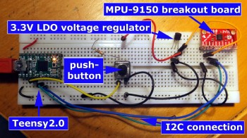
Here you see a photograph of the breadboard:
As you can see, the layout is very simple:
- The MPU-9150 is connected to ground and 3.3V through a Voltage regulator.
- The MPU-9150 is connected to the Teensy2.0 through 2 wires, the I2C connection.
- A pushbutton with a 10K pull-up resistor is connected to ground and the Teensy2.0
- The Teensy2.0 is connected to the PC via a USB cable.
- (Notice that the Interrupt pin on the MPU-9150 is not connected! More on that below).
In order to understand why I chose this particular setup, it helps to look at my history with the MPU-9150.
History
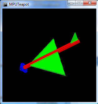
I first looked at the “MPUTeapot” example for Processing, included in the Arduino MPU6050 library at Github. Using Processing (version 2.0b6) on my PC, and the MPU6050_DMP6.ino sketch on a Teensy2.0, I was easily able to get the example running (of course I had to install the I2Cdev libraries for the Arduino, and the ToxicLibs libraries for Processing to get it to run), with the setup as displayed on the photo above. (The push button is not used in that case). The Teapot example is actually a simple airplane, 
which mimics the movements (rotations in all 3 axes) of the breadboard on the PC. Processing is connected to the Teensy by a serial connection (through the USB connection). In order to make a similar connection to Unity, my next step was to adapt the Processing code to C#. In short, this failed miserably. Based on various websites and my tests, I noticed
- event handling is not built in the Mono Serial Port code – so any examples based on that will not work in Unity.
- “int len = _SerialPort.BytesToRead” did not seem to work
- ReadByte(), as in “byte tempB = (byte) _SerialPort.ReadByte();” did seem to work, but only sometimes and at best a few seconds …
- ReadLine() is used in the code by Tiuri de Jong, “Unity Arduino Serial Connection“, and this seems to work without problems (at least on a PC).
This convinced me that I should take the approach by Tiuri de Jong as the basis for my serial connection. In turn, this then lead to my Arduino sketch and Unity application:
The Arduino sketch
The Arduino sketch that I use is basically a combination of the standard MPU6050_DMP6 example, by Jeff Rowberg and RGSteele, and the “Unity Arduino Serial Connection” by Tiuri de Jong. I used Arduino 1.0. In order to get the sketch to work, you must
- Download my own version of the Unity Arduino Serial connection: I made it into a library. So you must unzip the contents into a directory in the Arduino “libraries” directory. E.g., in my case the files will go in “D:\Mijn projecten\Arduino\arduino-1.0\libraries\ConnUnity”.
- Then download all the files to run the MPU6050_DMP example. I.e., create libraries for I2Cdev and MPU6050 similarly to the ConnUnity library.
- (Restart the Arduino IDE to find the libraries)
- (You could first try to run the standard MPU6050_DMP example with the setup above, in combination with Processing, just to make sure everything works. The only thing I had to do to run the example was comment out the “while (!Serial);” line in Setup)
- Now compile my Arduino sketch and upload to the Teensy.
In combination with the Unity application, it should work. The Arduino Serial Monitor can also give you a lot of information.
How does it work, i.e., what did I add/change?
What did I add/change in my Arduino sketch, relative to the standard MPU6050_DMP6 example?
I have made a separate page explaining all the details of the Arduino sketch.
The Unity application
I used Unity 3.5.1 on a PC. Here is a zipped Unity package which you can include in your own applications to test the Light Saber. (The light saber model which I used in the video is not included, since it is not for distribution – however, you can easily get an FBX light saber model on Turbosquid for a few dollars).
What do you need to do to get the Unity application running?
- Unzip the zipped Unity package, and store the “simpleLightSaber.unitypackage” somewhere on your hard drive.
- Open Unity, and (in the “Project” panel) import the package by right-clicking and selecting “Import Package > Custom Package“.
- You will likely get an error message saying “The type or namespace name `Ports’ does not exist in the namespace `System.IO’.” (This error occurs, because we are going to use a Comm Port for our connection.) You can correct this by going to menu “Edit > Project Settings > Player” and changing the Api Compatibily Level under Optimization from the standard “.NET 2.0 Subset” into “.NET 2.0“.
- You have to set the correct COM port as the value of the “COMPort” variable in the GUI Arduino Serial Script attached to the “actual_pivot” object. Finding out which COM port the serial connection uses can be done with the Windows “Device Manager”: connect the Teensy via USB to the PC, and check which COM port it uses.
- After connecting the Teensy and setting the COMPort value, you can run the Unity program!
How does it work?
I used the Unity program supplied with “Arduino Serial Connection” as a starting point. A separate page explains the details of the Unity program.
Interrupts
In the MPU6050_DMP6.ino sketch, the authors specifically state “”this sketch depends on the MPU-6050’s INT pin being connected to the Arduino’s external interrupt #0 pin.” However, as you may notice from the breadboard photograph above, in my setup there is no wire connected to het MPU-9150 INT pin (i.e., the rightmost pin on the breakout board). This is due to three reasons:
- I saw a picture here of the breakout board, without a wire connected to the INT pin.
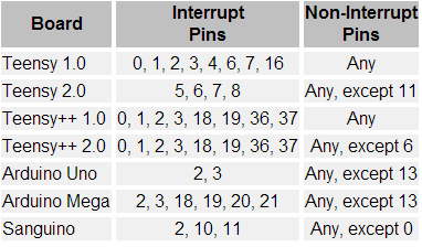
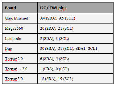
- Since the interrupt pin 0 on the Teensy2.0 coincides with an I2C pin (see tables below), I did not know how I could use the interrupt pin #0 at all. The same thing applies to the Teensy++ 2.0. (As you will see below, this is a little short-sighted).
- And the sketch seemed to work anyway (as long as I put my own code not in the “while (!mpuInterrupt …” part)
On second thought, I realized that although the setup works, it is not “proper”. I realized also, that I can use another interrupt, one not coinciding with an I2C pin. This only requires a small change in a single line in the Arduino sketch:
attachInterrupt(0, dmpDataReady, RISING);
Instead of using interrupt #0, we could change the 0 to a 2, and use interrupt #2 (pin 7 on the Teensy2.0) or a 3 for interrupt #3 (pin 8 on the Teensy2.0), and then there would be no conflict with the I2C pins. Indeed, I tried it (moving my “receiveQuaternion … processSerial..” code into the “while (!mpuInterrupt …” loop), and it works very well! I left the setup as it was since I had no problems with it, but I felt that I should inform you what the right way to do it is. 😉
Below, you find the I2C pins for various boards (information combined from here and here).
Conclusion
All in all, it is now easy to use the MPU-9150 functions to control an object in Unity! There are still some issues left unexplored, e.g.,
- It works only on a PC, not on a Mac. I am not sure what the best way to make such a connection on a Mac is. Recently I heard about Uniduino, an asset on the Unity Asset store, which looks very promising.
- Does the serial connection Unity-Arduino from Tiuri support output from Unity (e.g., controlling a LED on the Arduino from Unity)? I am not sure, I have not tested it yet, and Tiuri’s code comments are not promising … but it should not be too hard to get it working.
- The connection from the PC to the Arduino board should preferably be wireless (you want to wield an actual model light saber!). I recently bought a “bluetooth serial module” on eBay, and I am hoping that a wireless connection will be easy.
- My “library version” of the Unity-Arduino connection made by Tiuri de Jong could be drastically improved.


Sorry, het is niet mogelijk om te reageren.